Libre Router Basic RF Validation

Dear Sir,

I am Sagar Mistry from System Level Solution Pvt Ltd(India).

I required Technical support regarding Libre Router Basic RF Validation of Both 2.4GHz and 5.1GHz Radio.

We have purchased a 3x Libre router and using the same for further development.

I need to perform the following basic rf validation on it.

  1. Conductive output power measurement in Un Modulated mode
  2. Conductive sensitivity test( 1000 PER Packet test and check RSSI Value of each packet in receive mode)
  3. Channel selection
  4. Data rate selection
    5)Mode selection(a,b,g,n)

Can anyone help me to get the above configuration details in the libre router for 2.4GHz radio and 5.1GHz radio?

I have attached the following image for more reference.

Image1: Existing firmware loaded information of Libre router

Request you to guide me in this regard in more detail.

Hi Sagar!
What is the objective of the RF validation? Are you trying to perform a type aproval for the LibreRouter in India?

Most if not all the information you need is available in the homologation manual here https://gitlab.com/librerouter/boards/-/wikis/Wireless-homologation-tests-manual

Also here are more info on some rf validations already done: https://gitlab.com/librerouter/boards/-/wikis/Homologation-Standarization-Type-approval

Dear Sir,

Thanks for the valuable guidance and details.

Yes, we are planning to use this libre router in India, and before proceeding with the further development and order we need to evaluate basic rf validations on it.

Can you please help me to configure the Libre router in Receive mode and get the RSSI level of the packet received from the other node to measure the conductive sensitivity of the device?

As I haven’t find the details in this regard.

For the WPC Certification in India, Regarding the RF Firmware requirement, we required the support of unmodulated CW mode and 100% duty cycle modulated mode with channel and power level change configuration in the DUT.

It will be good if you guide me in this regard.

I would use a monitor interface (explained in the wiki https://gitlab.com/librerouter/boards/-/wikis/Wireless-homologation-tests-manual) and use tcpdump to record the packets of the wifi interface and use wireshark to view them in real time, for example using the following command:
ssh root@10.13.0.1 "tcpdump -U -w- -i mon0" | tee roteador2.pcap | wireshark -i - -
You will have to install tcpdump in the LibreRouter running opkg update and then opkg install tcpdump (plug the wan interface to the internet).

Using the TX99 mode you should be able to do the modulated mode as eplained in the wiki. I don’t know how to configure the radios to do CW. You can serch the internet using the following keywords: TX99 CW ath9k. ath9k is the driver. You may contact a representative of
Qualcomm in India so you can receive support from them.
Good luck!

Dear Sir,

Many thanks for the valuable guidance regarding the above.

Based on the instructions provided by you, I am getting the following error as shown in the below image.

Request you to guide me further in this regard

.

Hi!
Ok this may happen for two reasons:

  • the image is invalid (check the md5sum)
  • the image is valid but you are upgrading from some specific version (maybe LROs 1.4). In this case use safe-upgrade upgrade --force name_of_the_firmware.bin

Dear Sir,

Thank you so much for your valuable guidance and suggestion.

I have successfully loaded firmware and from that, I measured Continues Modulated Signal(100% Duty cycle) using monitor mode interface.

Can you please guide me regarding how to enable CW Single Tone(Without Modulation) Signal in both wifi radios to measure the Total Radiative power test on the router with the antenna inside the anechoic chamber?

Regarding the above, I have raised the support required to the Qualcomm team but they haven’t provided me any support in this regard.


Regarding the Dragino Libre Router Conductive Sensitivity mention in the Radio specification,

What should be the pass criteria considered regarding the PER for both radio in the conductive sensitivity? exa: 1% PER or 10% PER

We required conductive sensitivity details for the below Mode and data rate.

  • 802.11a Mode, 54Mbps

  • 802.11n(40MHz), MCS7


Awaiting your earliest reply.

Dear Libre Team,
Request you to help me in this regard at the earliest.

Maybe the radio has the option to do unmodulated CW but I am not aware of it.

Dear Sir,

Do you have any idea regarding the below test configuration inside the Libre router?

I think that you have to use the QSDK firmware to use art.exe, but I never tried

Okay Sir,
Thank you so much for the constructive support so far.

Dear Sir,

I found the following information related to QSDk firmware and ART tool.


  1. Setup Atheros ART Tool on Win PC

1.1 Download the following files from: http://www.dragino.com/downloads/tmp/

Calibrate.zip  - The AR9558 calibrate tool files. 

MCR_79_Installer.exe - MCR79 DLL installer required for tool. 

ART2.zip - Data file for the tool. 

1.2 Unzip the Calibrate.zip file into a suitable working directory on your Windows PC.

1.3 Run the MCR_79_Installer.exe file to install the required DLL.

1.4 Unzip the ART2.zip and place the file into the C:\ directory of your Windows PC.

  1. Setup the firmware on the board

2.1 Install QCA u-boot to match ART firmware

The “u-boot” file is available at:
http://download.villagetelco.org/firmware/lr/CalibrationFirmware/

Note: This u-Boot requires a 16MB SPI flash chip to be used.

CAUTION Take great care with this procedure because if you mess it up you will need to re-flash the
SPI chip in a programmer!!

The installation procedure from u-boot command prompt is as folows:

tftp 82000000 u-boot
erase 1:0-4
cp.b 0x82000000 0x9f000000 0x30000
reset

The board will restart using the new u-Boot.

2.2 Upgrade the board firmware (via u-boot) to the QSDK firmware which supports the ART tool.
The firmware (rootfs and kernel) is in the Calibrate zip under:

Calibrate\firmware

This firmware is also available at:

http://download.villagetelco.org/firmware/lr/CalibrationFirmware/

The upgrade method is:

tftp 0x80060000 rootfs
erase 0x9f050000 +0xE30000
cp.b 0x80060000 0x9f050000 $filesize

tftp 0x80060000 kernel
erase 0x9fE80000 +0x170000
cp.b 0x80060000 0x9fE80000 $filesize

2.3 Install the ART partion data:

tftpboot 0x80000000 art.new1
erase 0x9fff0000 +0x10000
cp.b 0x8000000 0x9fff0000 0x10000

2.4 Re-boot the board

reset

The board will restart and run the new firmware. It will have 192.168.1.1 IP after boot.

Telnet to this IP and run:
/etc/init.d/art start

This will start the QCA art software, and now we can use ART tool in the Windows PC to control the wifi parameters.

2.4 Check board operation

Wifi is disabled by default in the QCA firmware.
The /etc/config/wireless file defines an AP interface for 2.4GHz and 5GHz operation.

Test the wifi operation by commenting out the relevant “disable” line (eg the ‘wifi0’ 2.4GHz section for LibreRouter).

Run the ‘wifi’ command to start the wifi and check that the ‘ath0’ interface appears in the ‘ifconfig’ output, and
that the AP is visible on a wifi client such as your PC.

Restore the ‘disable’ line and run ‘wifi’ command again before continuing with the QCA tests below.

  1. Run the QCA Tool

3.1 Connect your PC to the board using an Ethernet connector.

The board will assign an IP address to the PC with DHCP. Check that you can ping the board at its IP address.

3.2 On your PC, in the directory where you placed the Calibrate software, run the utility

...\9558\art2_ver_4_9_844_release\bin\art_gui.exe.

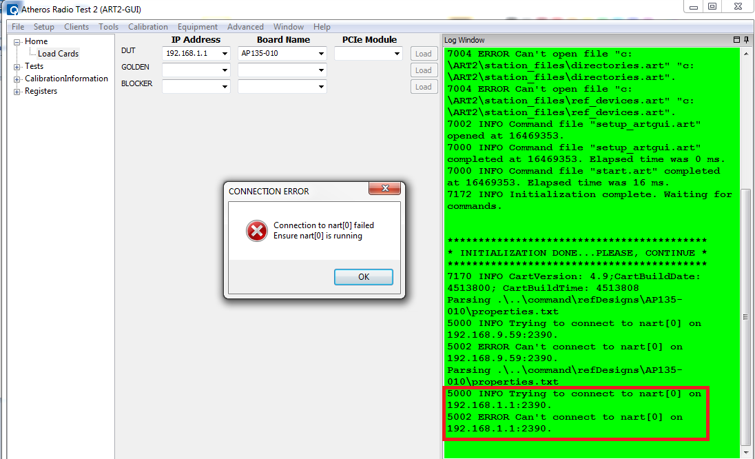
You should then see the application start up and display the “Home / Load Cards” screen and the statup log in
the green area on the right. The log will show “INITIALIZATION DONE PLEASE CONTINUE” if all is well.

3.3 In the DUT section, under IP address, put the IP address: 192.168.1.1.
In the Board Name field select the board “AP135-010”.
Leave all other fields blank.

Click on the “Load” button on the right of the DUT fields.
The log will show the connection attempt to the board, and end with “6000 INFO Loaded Card” if all is well

3.4 In the left hand menu, click on “Tests” and then on “ContTx”
Click on the “Start Transmit” button to start transmitting a signal, and “Stop Transmit” to stop.
Select the required Tx Chain to test from the “Tx: masks” drop down list.
Select the duration of the test from the "Packet count: drop down list.

3.5 In the left hand menu, click on :CalibrationInformation" and “Operations”.
You can back up a record of all the calibration data to a text file by clicking on the “Backup storage device
” button.
You can read and write individual calibration parameters by selecting the required field and clicking on the “Get”
and “Set” buttons.


Startup of the QCA “/etc/init.d/art” software on the board

root@OpenWrt:/# /etc/init.d/art start
find: /sys/devices/platform/spi*: No such file or directory
[ 1253.380000] ****Address of trace_timer :8640e610
[ 1253.420000] ath_hal: 0.9.17.1 (AR5416, AR9380, REGOPS_FUNC, PRIVATE_DIAG, WRITE_EEPROM, TX_DATA_SWAP, RX_DATA_SWAP, 11D)
[ 1253.450000] ath_rate_atheros: Copyright © 2001-2005 Atheros Communications, Inc, All Rights Reserved
[ 1253.470000] ath_dfs: Version 2.0.0
[ 1253.470000] Copyright © 2005-2006 Atheros Communications, Inc. All Rights Reserved
[ 1253.490000] ath_spectral: Version 2.0.0
[ 1253.490000] Copyright © 2005-2009 Atheros Communications, Inc. All Rights Reserved
[ 1253.500000] SPECTRAL module built on Jan 5 2017 16:12:49
[ 1253.520000] ath_tx99: Version 2.0
[ 1253.520000] Copyright © 2010 Atheros Communications, Inc, All Rights Reserved
[ 1253.560000] ath_dev: Copyright © 2001-2007 Atheros Communications, Inc, All Rights Reserved
[ 1253.650000] init_ath_pci[656] By pass AHB bus scan
[ 1253.660000] ath_pci: SmartAntenna-DRT-0.1 (Atheros/multi-bss)


Partition info for QCA firmware

root@OpenWrt:/# cat /proc/mtd
dev: size erasesize name
mtd0: 00040000 00010000 “u-boot”
mtd1: 00010000 00010000 “u-boot-env”
mtd2: 00e30000 00010000 “rootfs”
mtd3: 00490000 00010000 “rootfs_data”
mtd4: 00170000 00010000 “kernel”
mtd5: 00010000 00010000 “art”
mtd6: 00fa0000 00010000 “firmware”


Can you please check the above details and help me that is it helpful or not?

1 Like

That may be helpful yes!

Dear Sir,

With reference to the above detail, I have tried to download the above files and ART2 utility for AR9558/QCA9558 Chipset for 2.4GHz Wi-Fi Radio.

We have successfully loaded ART2 Firmware with help of the TFTP server inside Dragino Libre Router.

After that, I am getting the following error while connecting with DUT(Dragino Libre Router) with the ART2 Utility.

Also attached the document for more reference on below link : https://dokumen.tips/documents/ar93xx-art2-reference-guide-mkg-15527.html

Can you please guide me further if you have any idea in this regard?

Hi! Check that the kart process is running inside the board (i think you can stop /usr/bin/kart stop and start with /usr/bin/kart start). You may have to ssh to the board or use telnet (user root password admin maybe?). Check that you can connect to the port 2390 after starting kart).

Dear Sir,

Thank you so much for the valuable guidance and support in this regard.

I have successfully solved the above error and get the nart(0) connection with the ART utility by connecting the ethernet cable to the WLAN port of the Libre router to the Laptop.

Also, I have changed IPV4 settings to DHCP Configuration, so the laptop will take IP(192.168.1.1) from the libre router.

now I am able to load the card settings inside ART utility for nart(0) connection and 2.4GHz Radio By default and performed various tests like Transmitter Frequency offset in single carrier mode(+/- 110 kHz in 1 board) and Transmitter Modulated packet test.

but, unable to set the configurations inside utility for 5 GHz Radio Module which will be connected using PCI-E interface and can be configured inside utility using nart(1) successful Connection.

Getting nart(1) Communication failure error in the utility same as nart(0).

Can you please help me in this regard further?

Now I need to Evaluate the 5GHz Radio(Chipset AR9582) which is connected to a Mini PCI Express port with MCU QCA9558.

I am getting the following error on the ART utility.

I am unable to configure the frequency/Channel selection option inside the utility.

Can you please guide me further related to the configuration of 5GHz radio settings inside the ART2 utility?

Hope to hear from you at the earliest.

I believe that you need to plug the 5ghz mPCIe board directly to the computer for the ART utility to work (at least I know that connecting the 5ghz board directly to the PC works, I don’t know if connecting it through the librerouter works also). You may need a PCIe to mPCIe adapter.

Dear Sir,
Can you please guide me further regarding the connections of the 5 GHz mPCIe module to the PC?
Actually, I have no idea about this regard.